The FlySky TH9X transmitter (
Figure 1) is a great value in a 2.4 GHz radio. It’s also sold rebranded as the Turnigy 9X, and the Imax 9X, and these radios have proven extremely popular and reliable over the years. For a fraction of the price of an 8-channel JR or Futaba product, you get a good quality, durable radio that should last you for many years.
 |
| Figure 1: The FlySky TH9X Tx and included 8-Ch Rx. This is a great radio for the price, and is very popular, also sold rebranded as the Turnigy 9X. |
The 9X radios do have some drawbacks, but most of them can be addressed with a few easy and cheap upgrades. In this build log we show you how to replace the 9X’s stock AA battery holder with a 2700 mAh LiPo that will last hours between charges. If you’ve just purchased the 9X radio, this is one of the first things you’ll want to upgrade, otherwise you’ll be spending lots of money replacing AA batteries, and won’t be getting much flying time in between battery changes.
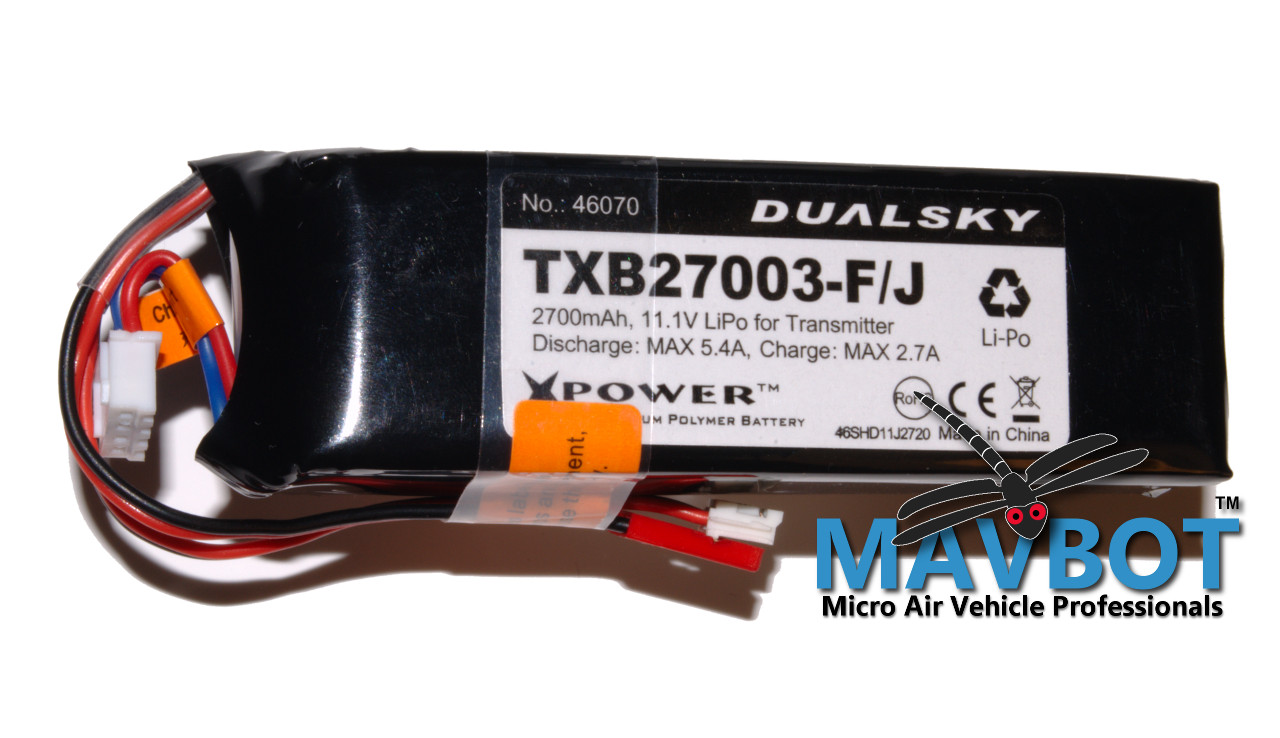
The LiPo we’ve chosen for this build is DualSky’s 2700 mAh transmitter LiPo (
Figure 2). It’s specially designed to fit the tight space of a Tx battery compartment, and according to DualSky’s website you can even charge it using the the Tx’s existing charge port, as the cells are very carefully matched during production. However, in consideration of getting the maximum battery life cycles and due to the risk of fire if a cell is overcharged, we suggest using a balance charger designed for LiPos, and never exceeding 2.7A (1C) charge current.
 |
| Figure 2: DualSky’s 2700 mAh Tx LiPo battery is specially designed for JR transmitters, and also works well with the FlySky TH9X and the rebranded radios such as the Turnigy 9X. |
If you do use your Tx’s built-in charge port instead of a balance charger, we’d recommend balancing the battery after every few charges. DualSky’s LiPoMate battery cell voltage meter and balancer (
Figure 3) is great for this, and it’s keychain-sized, so you can carry it everywhere you fly.
 |
| Figure 3: DualSky’s LiPoMate Cell Volt Meter and Balancer. It tells you the voltage of each individual battery cell, and automatically balances them as you watch. Key chain sized, so it’s easy to carry with you to the field. Requires no battery or power source of its own, since it draws only minimal power and runs off the battery you’re balancing. |
Installation Procedure:
1. Use the Existing Tx Power Connector, or Not
When you take the Tx LiPo battery out of its package, you will notice it has three connectors: The 4-pin white balance connector, the two-pin red charge connector, and the 2-pin white Tx power connector (
Figure 4). The 2-pin white connector is the one that should be connected to power your transmitter. Unfortunately however, the power connector inside the TH9X’s battery compartment is 3-pinned. There are two solutions to this: The quick and easy way is to force the 2-pin connector on the battery into the 3-pin connector on the Tx. This works just fine, if you connect it with the correct polarity to the correct two pins. However it’s a messy solution, and if you ever have to take the battery out for some reason, you might forget which way to connect it back again (I would make a black mark with a Sharpie over the negative pin of both connectors, that way you’ll remember).
 |
| Figure 4: The DualSky Tx LiPo Battery comes with 3 Connectors: Tx power connector (white, two-pin), charge connector (red), and balance connector (white, four-pin). |
Note that the red charge connector on the battery will fit the Tx just fine, but it sticks out too far into the battery compartment, and you risk puncturing the battery if you force it into the battery compartment with that connector in the way. Also, you’ll have to remove it again every time you want to charge the battery with your LiPo balance charger, and it can’t be removed with the battery in the way.
2. Replacing the Existing Connector with the one from the AA Battery Holder
Rather than force the 2-pin connector on the battery into the 3-pin connector in the battery compartment, we decided to replace it with the 3-pin connector from the original AA battery holder. This is a little more work, but the end result is more satisfactory, at least aesthetically, and the original 3-pin connector will only fit one way, so you won’t need to remember how to connect it.
To do this replacement, you’ll first need to cut the connector off the old AA battery holder, and also cut the white 2-pin connector off the Tx LiPo battery. You’ll need to observe extreme caution when working on the battery connector side, otherwise you will end up shorting the battery leads, which will damage the battery.
To avoid shorting the battery leads, always cut them one at a time, covering the first one securely with heat shrink before cutting the second lead (make sure the heat shrink shrinks to a small enough diameter that it stays tightly on the lead while you’re working, and won’t slide off; we used 1.5-mm heat shrink to tightly cover a single wire).
Secondly, you should always cut the red and black leads at different lengths, so that the exposed ends, and later the solder joins, can’t short out by touching each other. If you cut the black wire shorter on the battery side then cut the red wire shorter on the connector side, and vice versa. This way they will match up correctly for the solder join. After the join, the uninsulated areas will be staggered so they can’t touch each other, and the total wire length for red and black will be the same. Since the joins can’t touch each other, at the end you can use a single piece of heat shrink over both wires. But inspect the joins carefully to make sure they are far enough part, and that there is no insulation damage, to ensure there is no risk of a short.
Be sure to put the piece of heat shrink over both wires before making the solder joins, since the heat shrink won’t fit over the connector once they are made. It needs to be small enough to cover the joins tightly, so it won’t slide back and expose them; we used 2.5-mm heat shrink to cover both wires. But slide it as far as possible from where you are working so it won’t shrink prematurely from the heat of your soldering. If you’re fast at soldering this should be no problem, but you can also wrap a piece of thin bare copper wire around the wires between where you are soldering and the piece of heat shrink; that will absorb some of the heat.
You’ll probably want to clamp the wires in a solder helper as pictured (
Figure 5) to hold them in place while you solder (in the picture notice the 1.5-mm heat shrink protecting the red wire that we’re not working with, and the 2.5-mm heat shrink ready to slide into place and then shrink once we’re finished with both joins). Make sure the teeth on the solder helper jaws aren’t going to squash or puncture the soft wire insulation. We added a couple extra layers of 5-mm heat shrink to the jaws on ours to prevent such damage from occurring.
 |
| Figure 5: Red wires in the solder helper ready to be tinned. Notice the black wire we’re not working on yet is protected from short with a temporary piece of 1.5-mm heat shrink, and a long piece of 2.5-mm heat shrink is positioned over both wires, ready to be slid over the joins and shrunk when we’re finished soldering. Also notice the 5-mm heat shrink over each side of each solder helper jaw, to protect the wire insulation from damage from the teeth. Multiple layers may be necessary, since silicone wire insulation is very soft. |
To make a join, first tin the exposed end of each wire individually, then position the ends alongside each other with good contact between them, and add some heat until the solder on them fuses. When you’ve done the first join, wrap it with electrical tape before removing the temporary heat shrink from the second battery lead to work on that; again never leave both battery leads exposed at the same time.
Once both solder joins are made, slide the heat shrink over them, double checking that the joins on red and black are far enough apart that no short is possible, and shrink the heat shrink over both joins with your heat gun. It should now look like this: (
Figure 6).
 |
| Figure 6: Heat shrink over both wires to protect the exposed areas. If you use a single piece of heat shrink for both wires like this, make sure the joins are staggered far enough apart that there is no possibility of contact. |
3. Installing the Battery in the Transmitter
Now you can install the battery in the transmitter. First connect the battery, then ease it into the battery compartment with the label side facing outward. Then carefully arrange the charge and balance wires and connectors into the remaining space so that they can be pulled out again when you need to charge or balance, without removing the battery itself (
Figure 7). Make sure nothing is protruding before replacing the battery compartment cover.
 |
| Figure 7: DualSky Tx LiPo installed into FlySky TH9X Tx. The charge connector (red), and balance connector (white, all but obscured by wiring) can be pulled out for charging/balancing without disconnecting or removing the battery itself. |
Now go fly your aircraft, without having to worry about buying huge quantities of AA batteries all the time!